
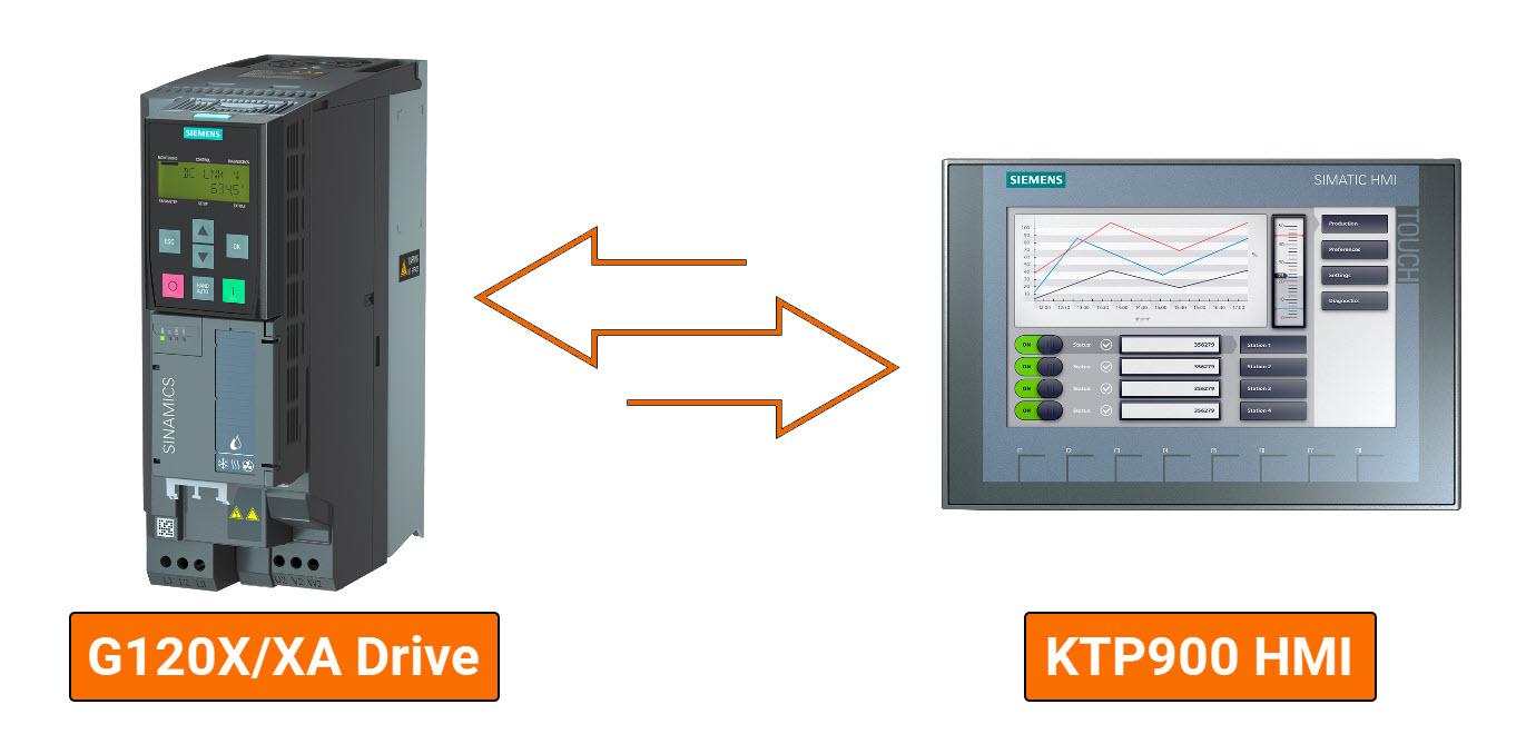
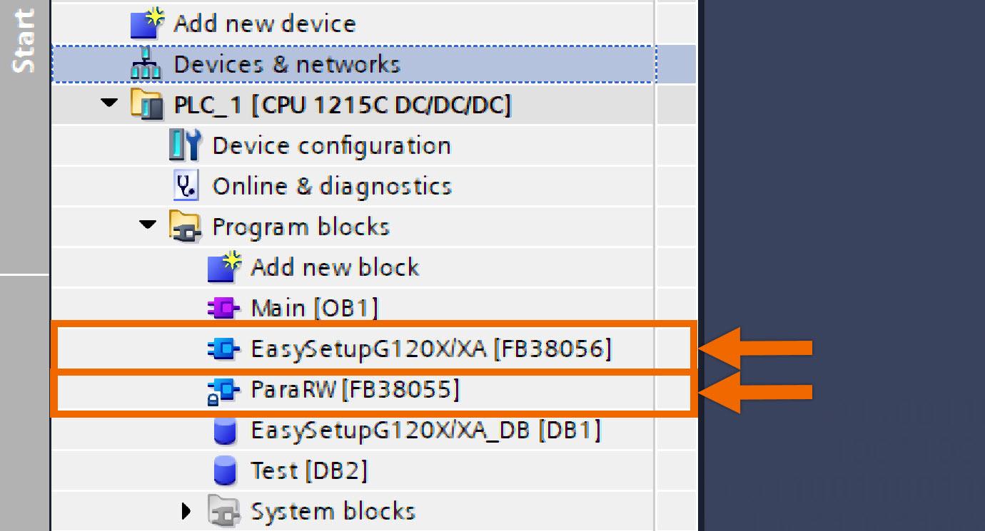
این آموزش روشی سادهشده برای راهاندازی درایوهای Siemens G120 ارائه میدهد که با هدف سادهسازی مراحل راهاندازی اولیه و نگهداری طراحی شده است. این برنامه شامل دو بلوک تابع است: «ParaRW» با شناسه FB38055 و «EasySetupG120X/XA» با شناسه FB38056.
ParaRW (FB38055): این بلوک تابع (FB) با استفاده از روشهای ارتباطی غیر دورهای برای خواندن یا نوشتن، به منظور تعامل با پارامترهای درایو بهکار میرود. از جمله قابلیتهای آن، امکان بازگرداندن پارامترهای درایو به پیکربندی کارخانه و نوشتن پارامترهای راهاندازی به صورت دستهای (Batch) میباشد.
EasySetupG120X/XA (FB38056): این بلوک تابع با بهرهگیری از ‘ParaRW’ (FB38055)، قادر است تمامی قابلیتهای گنجاندهشده در FB38055 را اجرا کند. علاوه بر این، به امکاناتی مانند کنترل سرعت از طریق PROFINET و رابط کاربری برنامهنویس برای اجرای دستورات درایو و پایش وضعیت لحظهای نیز دسترسی میدهد.
آنچه برای دنبال کردن این آموزش نیاز دارید:
شما باید نرمافزار TIA Portal را روی رایانه شخصی خود نصب کرده باشید. اگرچه این آموزش به نسخه ۱۸ اشاره دارد، اما اطمینان داشته باشید که سایر نسخههای TIA Portal نیز بهخوبی کار خواهند کرد.
شما باید با نصب فایل GSDML مربوط به سروو درایو مورد نظر خود در TIA Portal آشنا باشید.
شما ملزم به نصب نرمافزار SINAMICS StartDrive نسخه ۱۸ سرویس پک ۲ (SP2) هستید.
پیکربندی سختافزار
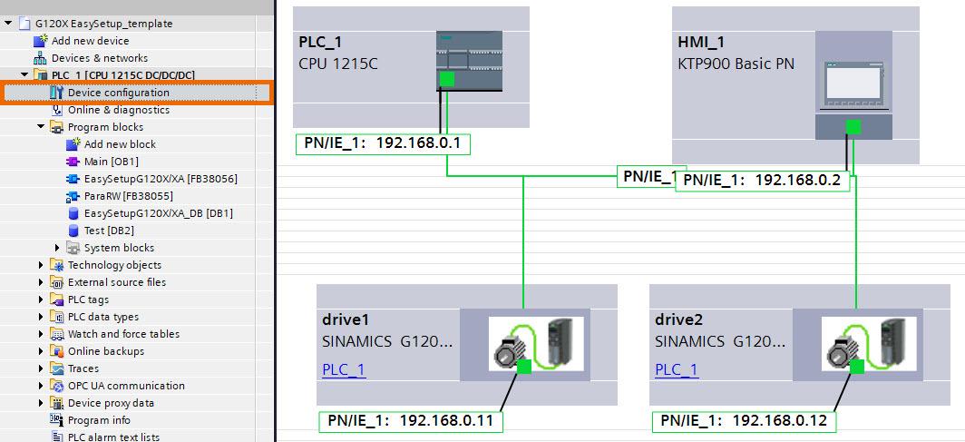
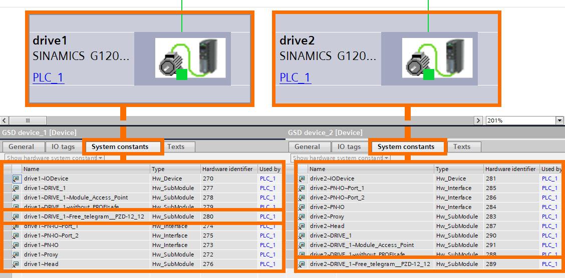
در چارچوب این مثال کاربردی، پیکربندی سختافزار شامل PLC مدل S7-1200، پنل HMI مدل KTP 900، و درایو G120X بهعنوان اجزای اصلی است. گذرگاه PROFINET امکان ارتباط اتصال میان درایو G120X، پنل KTP 900 HMI و PLC مدل S7-1200 را فراهم میکند. پیکربندیهای دقیق مربوط به آدرسهای IP و نام دستگاهها در شکل زیر ارائه شدهاند.
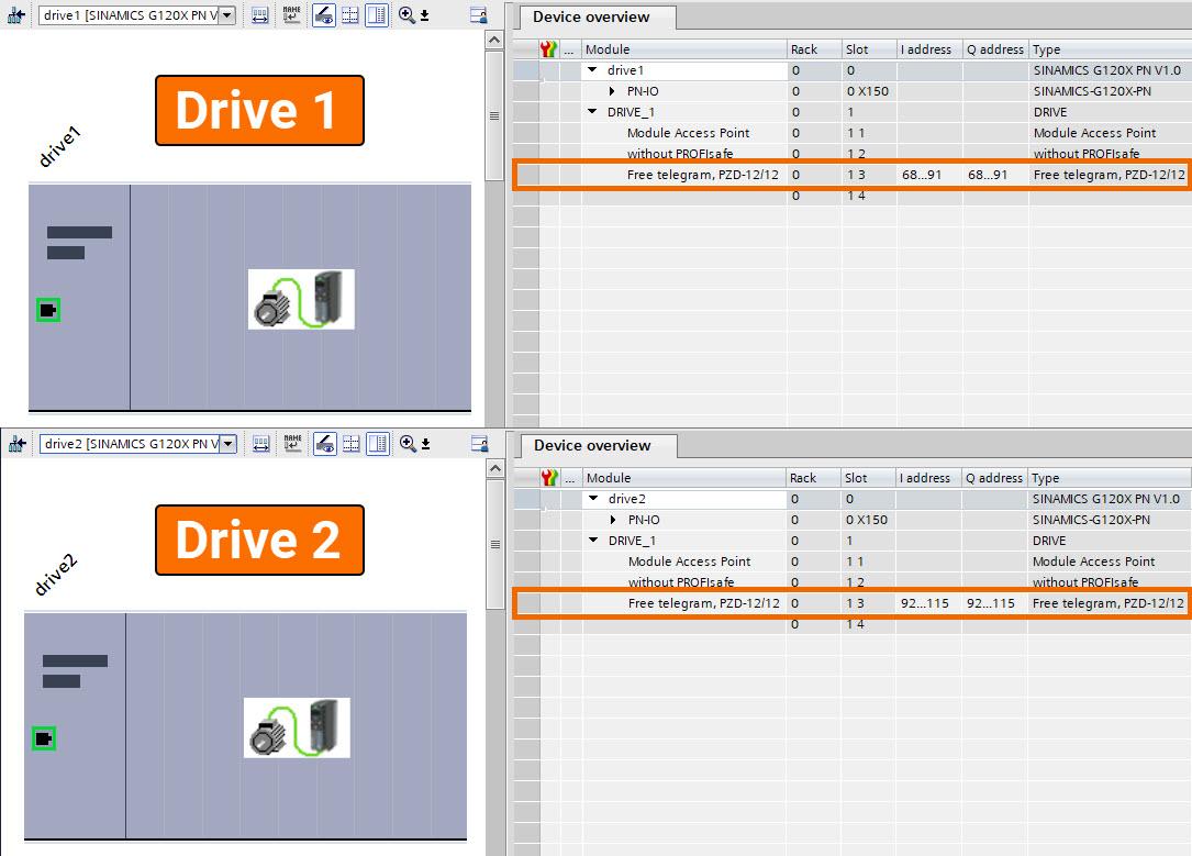
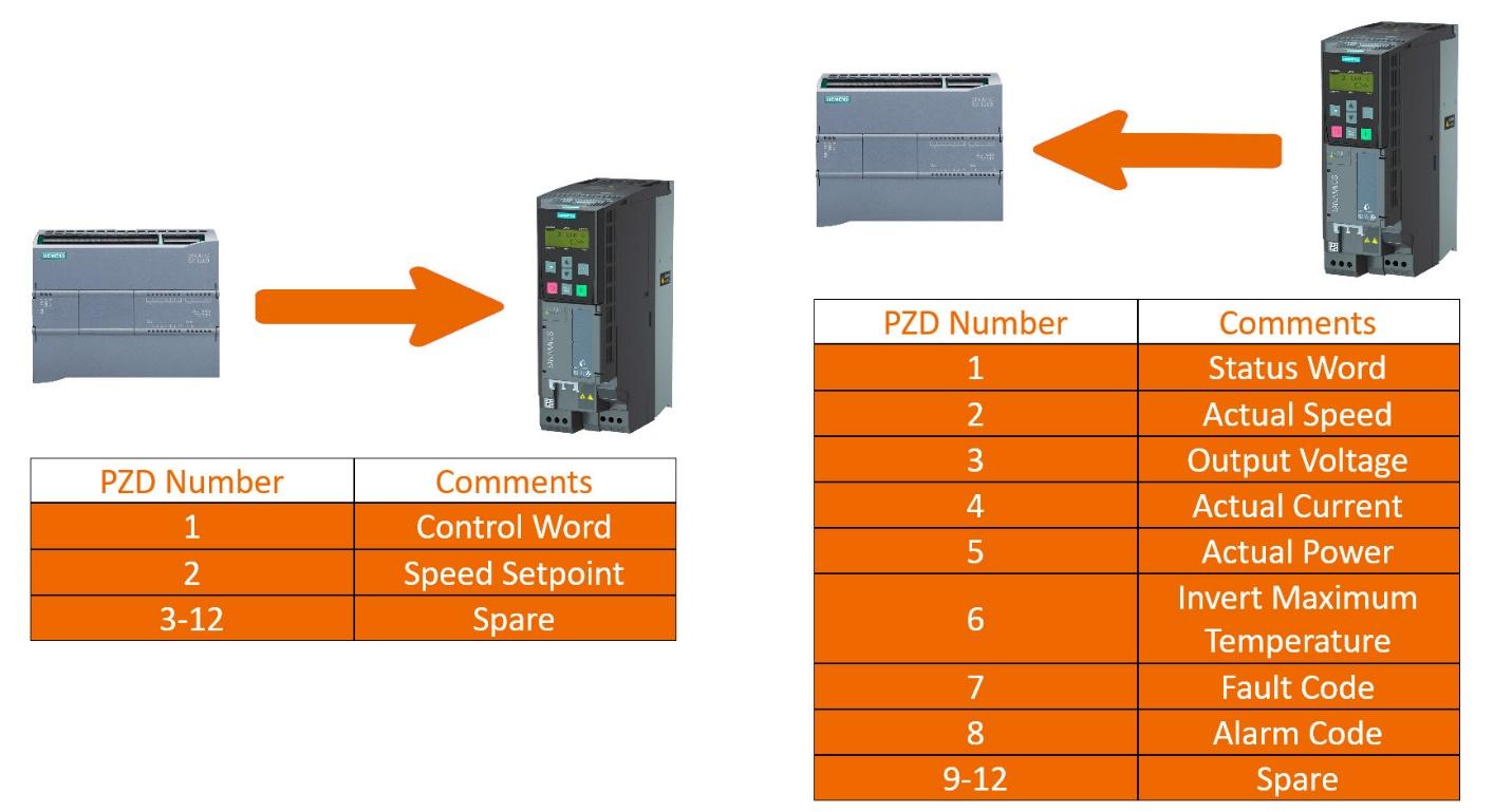
واحدهای G120X از طریق تلگرام آزاد ۱۲/۱۲ با PLC ارتباط برقرار میکنند و این امکان را فراهم میسازند که دادههای حیاتی مانند نقطه تنظیم سرعت (Speed Setpoint)، کلمه کنترل (Control Word)، مقادیر واقعی (Actual Values)، و کلمه وضعیت (Status Word) تبادل شوند.
فراتر از دامنه اولیه خود، این برنامه شرایطی را نیز پشتیبانی میکند که در آن بیش از دو مبدل (Converter) وجود دارد. مهندسان باید آدرسهای IP و نام دستگاهها را برای مبدلهای اضافی پیکربندی کرده و همچنان از پروتکل تلگرام آزاد ۱۲/۱۲ استفاده نمایند.
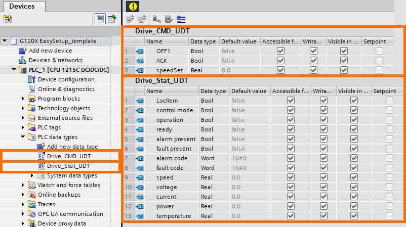
در قالب این پروژه نمونه، دو نوع داده PLC متمایز تعریف شدهاند:
Drive_CMD_UDT: این نوع داده ساختیافته (UDT) شامل دستورات کنترلی ضروری درایو مانند OFF1، ACK (دستورات تأیید) و SpeedSet (نقطه تنظیم سرعت) است. این UDT امکان کنترل مناسب درایو را فراهم میسازد.
Drive_Stat_UDT: این UDT شامل مقادیر واقعی (Actual Values) و کلمه وضعیت (Status Word) مرتبط با مبدل (Converter) میباشد.
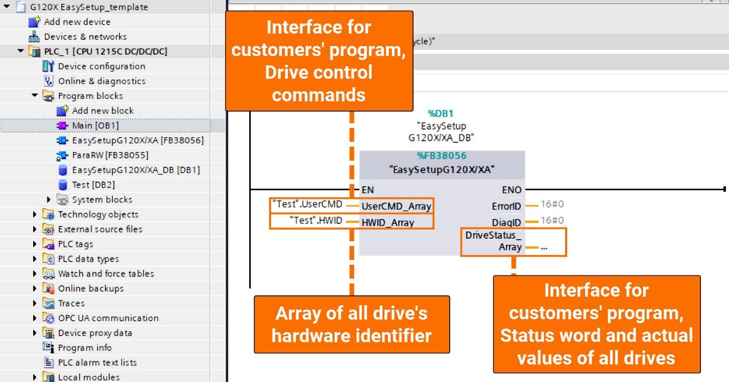
با استفاده از EasySetupG120X/XA (FB38056) برای فراخوانی ParaRW (FB38055)، مهندسان فرآیند راهاندازی را سادهسازی میکنند، بهطوریکه تنها کافی است FB38056 را در بلوکهای سازمانی چرخهای مانند OB1 فراخوانی کنند. در نتیجه، برنامه PLC دو عملکرد کلیدی را محقق میسازد: «راهاندازی سریع مبدل» و «تنظیم سرعت از طریق PROFINET».
راهاندازی سریع مبدل (Rapid Converter Setup):
با استفاده از دستورات برنامهنویسیشده، PLC بهصورت خودکار عملیات خواندن و نوشتن تمام پارامترهای راهاندازی را انجام میدهد، که نیاز به ورود دستی اطلاعات از طریق واسطهای Basic Operator Panel یا Intelligent Operator Panel را حذف میکند و در نتیجه، کارایی عملیاتی را افزایش میدهد.
تنظیم سرعت از طریق PROFINET (PROFINET Speed Regulation):
ارسال نقطه تنظیم سرعت (Speed Setpoint) و کلمه کنترلی (Control Word) از PLC به درایو با دریافت مقادیر واقعی (Actual Values) و کلمه وضعیت (Status Word) تکمیل میشود، که ارتباطی جامع و کامل میان کنترلر و درایو را تضمین میکند.
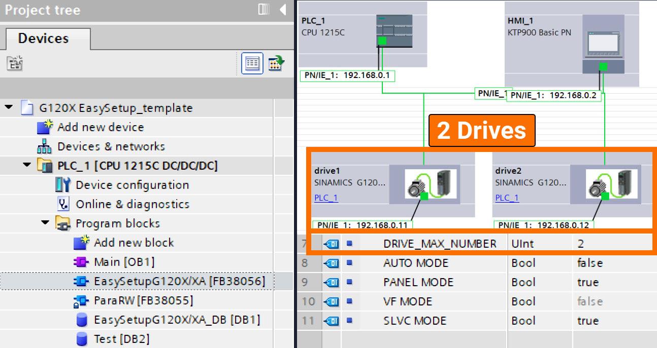
اطمینان حاصل کنید که مقدار ثابت DRIVE_MAX_NUMBER در بخش Interface از بلوک تابعی EasySetupG120X/XA بهدرستی با تعداد کل درایوها مطابقت دارد، سپس بلوک را کامپایل و فراخوانی نمایید.
در زمینه مثال کاربردی حاضر، که شامل دو درایو است، مقدار ثابت DRIVE_MAX_NUMBER بهدرستی پیکربندی شده و مقدار آن برابر با ۲ تعیین شده است تا با تعداد درایوها مطابقت کامل داشته باشد.
Obtaining the drive’s distinct hardware identifier entails navigating through the ‘Device view,’ selecting ‘Properties,’ and then accessing the ‘System constants’ section, as clearly outlined in Figure 3.4.
Two HMI screens, labeled ‘Monitoring’ and ‘Setup,’ have been generated within the framework of this template project, tailored to specific functionalities.
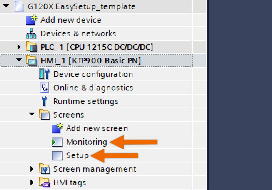
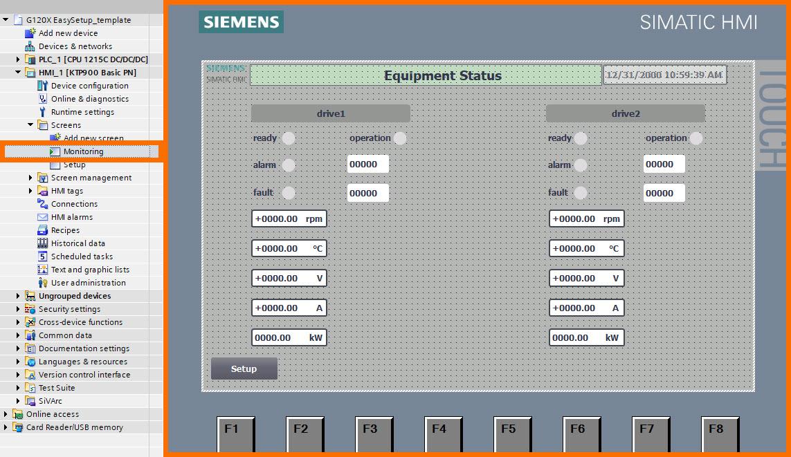
Monitoring Screen: Designed with monitoring in mind, this screen serves as a central hub, providing users with in-depth visibility into the status bits and real-time actual values across all drives.
Setup Screen: The focus of this screen is to streamline the commissioning process for the converter.
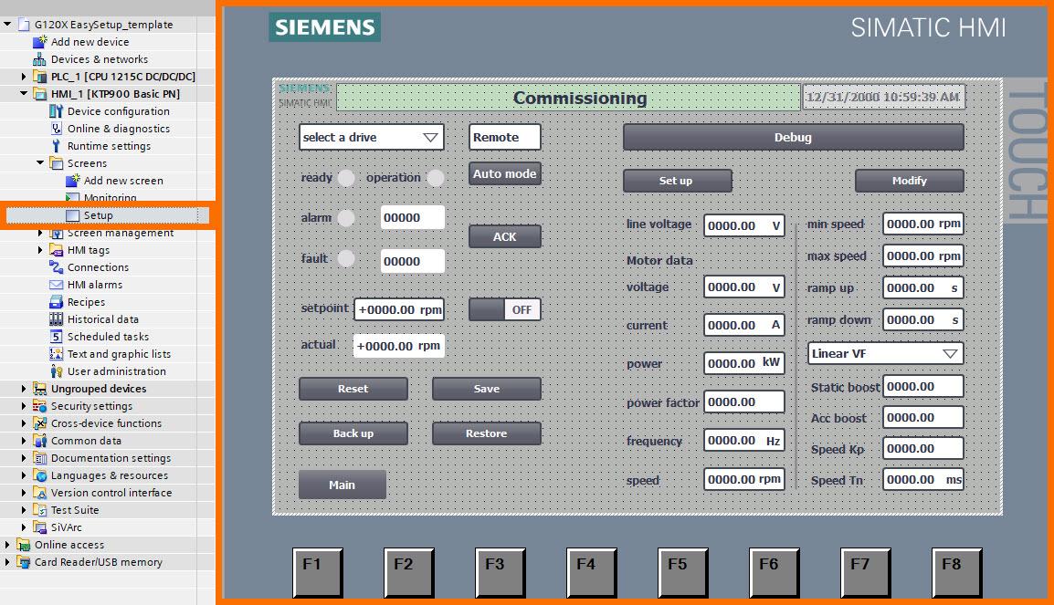
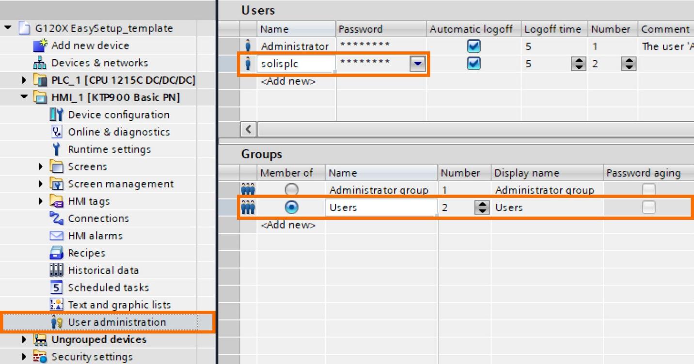
The default configuration takes the precautionary step of cloaking all setup function buttons to impede unauthorized access to drive parameters, fostering a secure operational environment. Display of these buttons is contingent upon the ‘Debug’ button being clicked and the correct user credentials entered, ensuring visibility is restricted to authorized users post-authentication.
The specified access credentials entail the username ‘solisplc’ and the associated password ‘123456’. Engineers are granted comprehensive authority to intricately modify the settings embedded within the ‘User Administration’ interface, as shown in Figure 4.4.
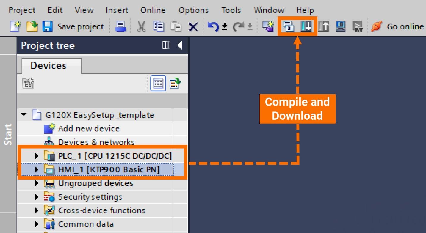
Before exploring the operation segment in-depth, it is imperative to fulfill two primary prerequisites: confirming the accurate configuration of IP addresses and device names for all drives and successfully downloading this project onto the PLC and HMI.
Let’s enable the display of setup function buttons. Launch the process by clicking the ‘Debug’ button, and proceed to enter the requisite password and username.
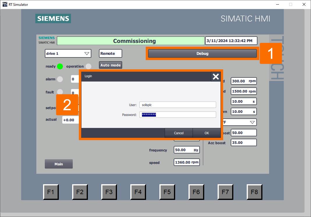
Clicking the ‘Debug’ button once more will result in the appearance of all setup function buttons.
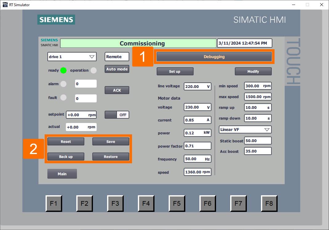
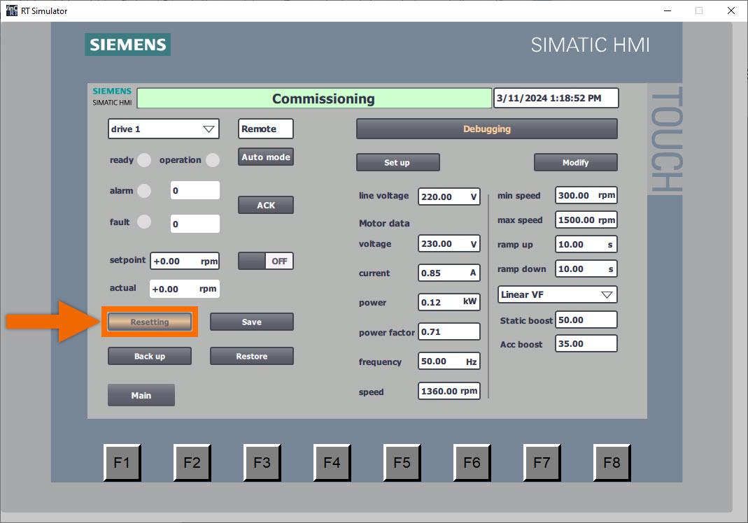
Proceed with resetting the drive parameters to their original factory configuration. Engage the converter’s factory setting restoration process by clicking the ‘Reset’ button to initiate the operation. Throughout this operation, the button will visually indicate ‘Resetting,’ with the background shifting to an orange hue and intermittently flashing to signify ongoing activity.
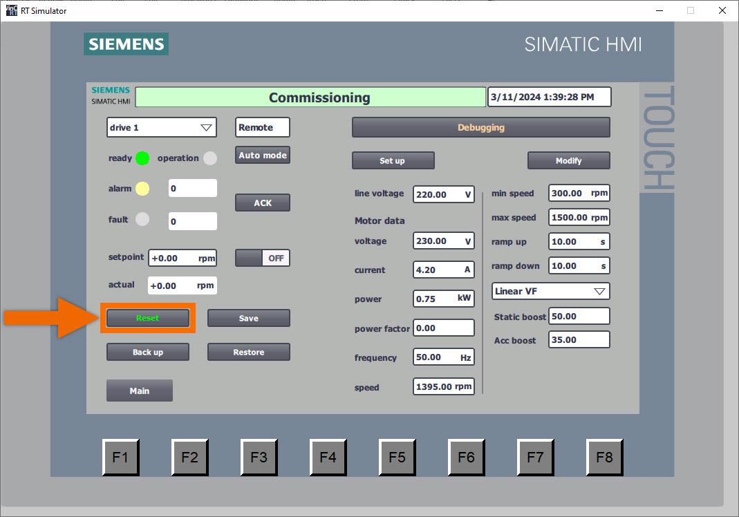
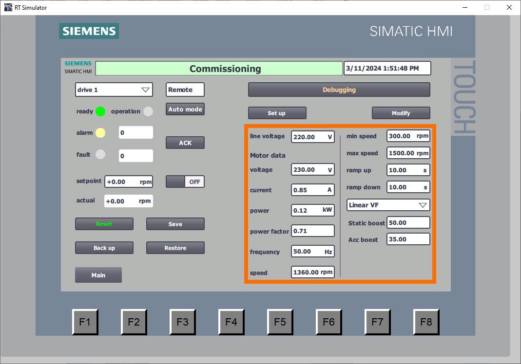
Once the reset process for all parameters is complete, the button will show ‘Reset,’ and the color of the text will transition to green. In addition, the HMI panel extends its display to include the default parameter setting of the converter.
Let’s undertake the task of batch-writing setup parameters. Ensure all values of setup parameters are meticulously entered via the HMI panel interface, addressing crucial variables such as motor data, voltage of the line, control mode of the drive, and ramp time. The remaining customized parameters have been intricately configured within the function block, sparing the user from the necessity of manual input through the HMI panel interface.
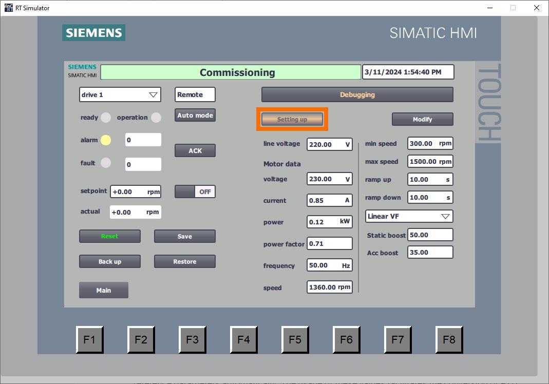
Trigger the PLC to begin batch writing of parameters by pressing the ‘Setup’ button. Throughout this operation, the button will visually indicate ‘Setting up,’ with the background shifting to an orange hue and intermittently flashing to signify ongoing activity.
Following the writing of all parameters, the button transitions to the ‘Set up’ display, while the color of the text elegantly changes to a vibrant green hue. The automatic activation of motor standstill identification results in the ‘A07991’ notification being displayed.
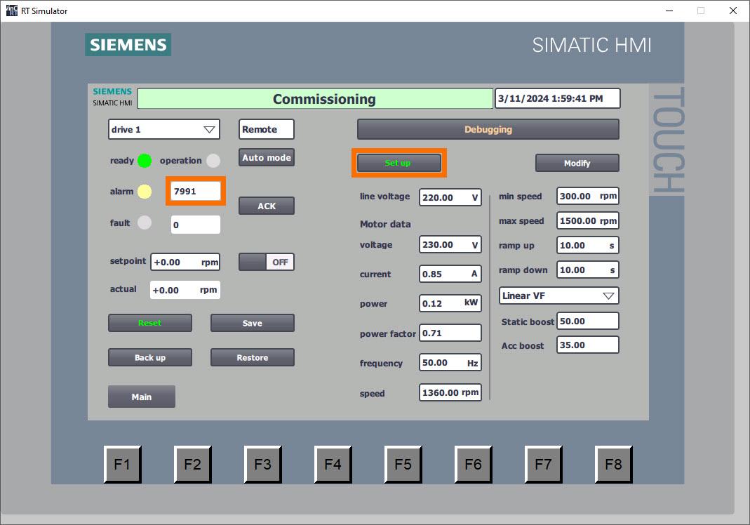
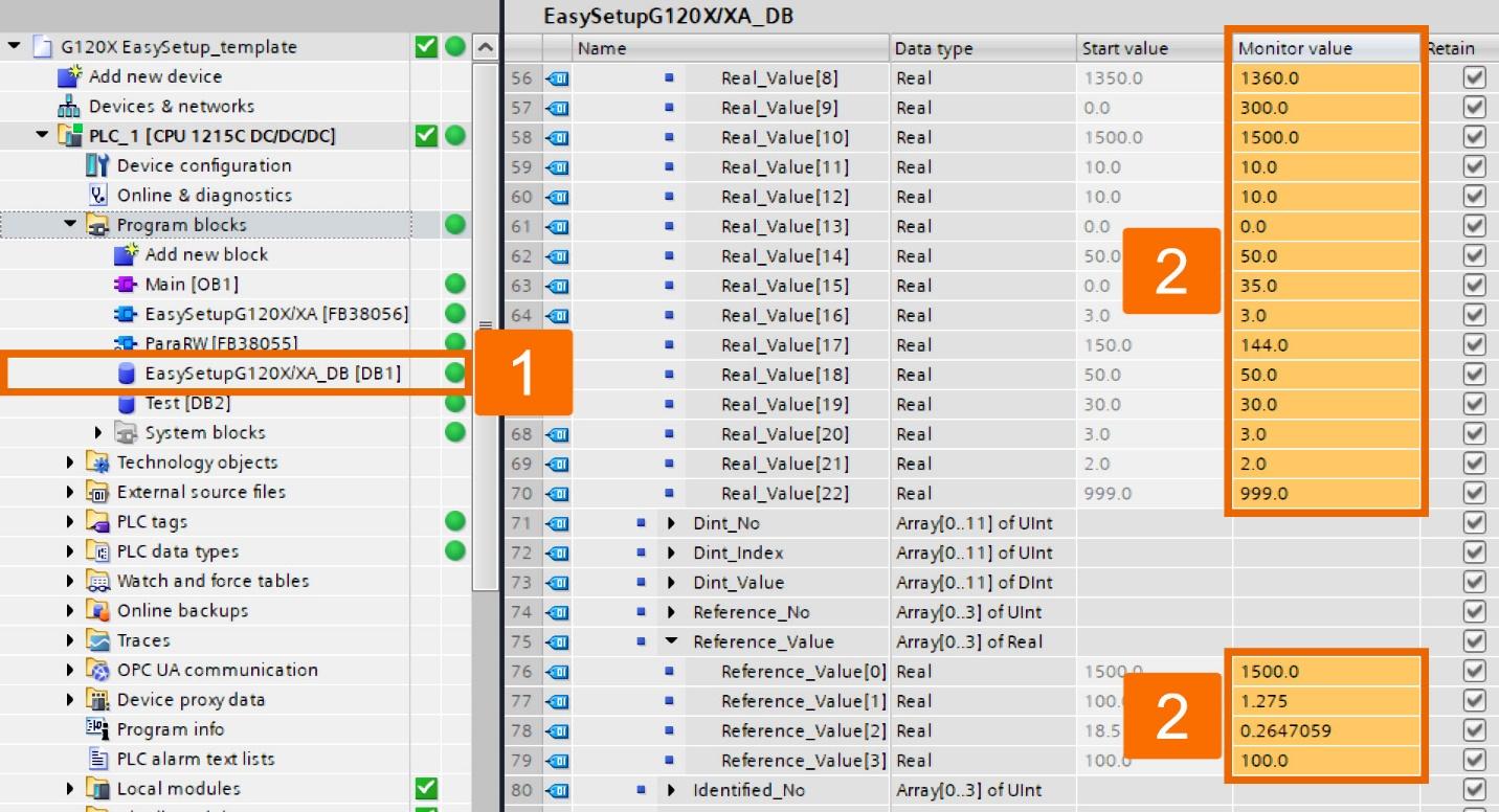
Following the completion of parameter writing, the PLC seamlessly engages in the retrieval of reference parameters automatically. The usage of these values facilitates the conversion of PZD data into actual values, incorporating the appropriate physical units.
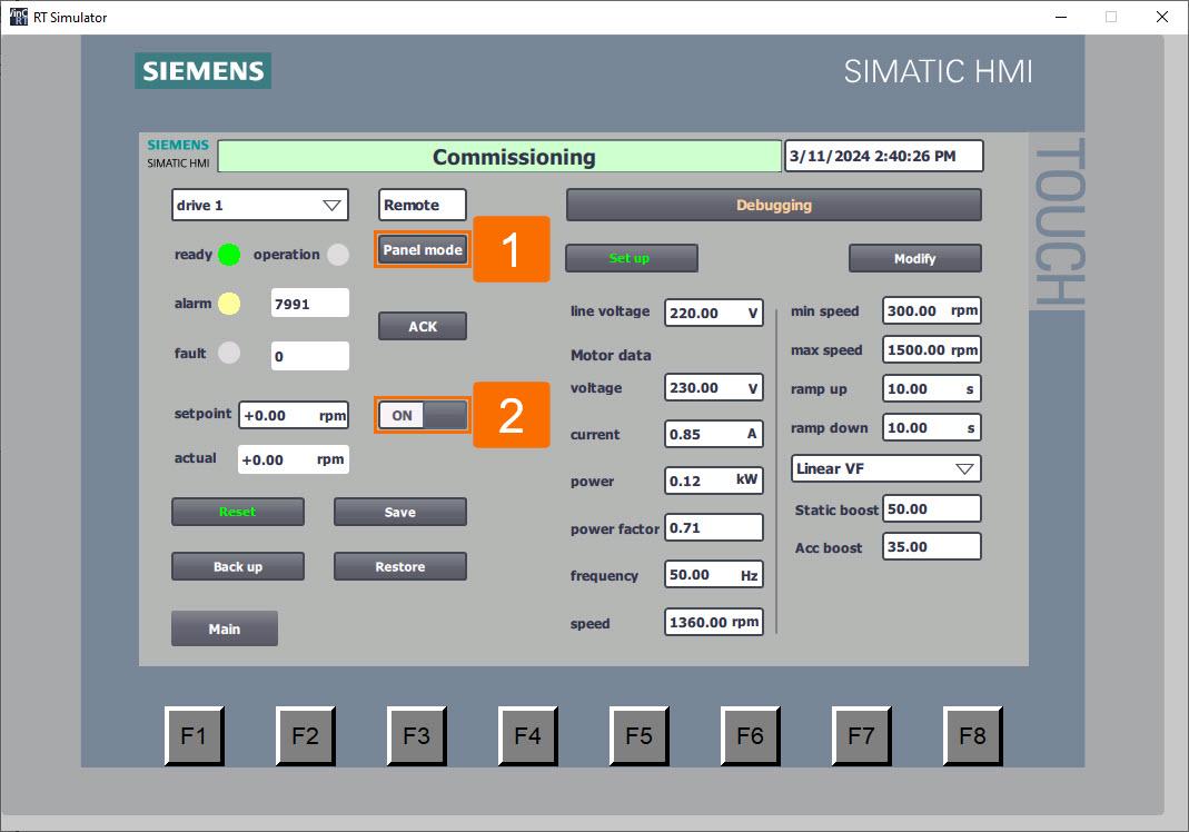
At this moment, employ the HMI panel controls to implement standstill identification. Following parameter setup, engagement of ‘Panel mode’ is possible by clicking the ‘Auto mode’ button, denoting the switch to HMI panel control of the converter. Activate the converter by clicking the ‘ON/OFF’ button; this triggers motor standstill identification.
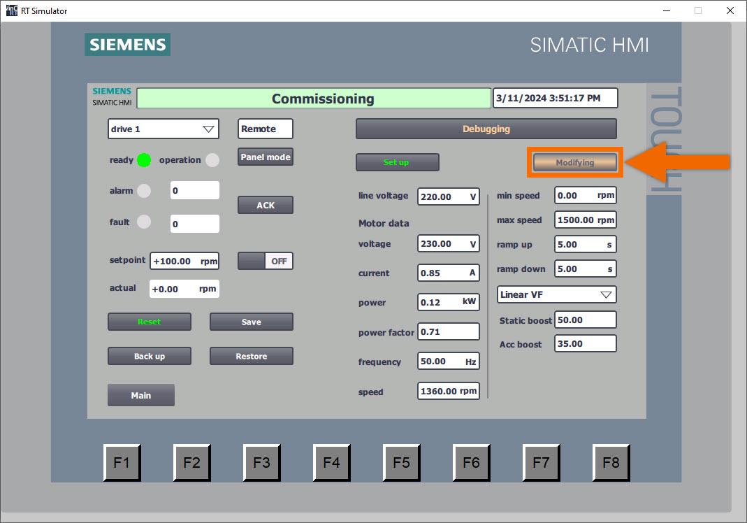
It’s time to adjust application parameters collectively in batch mode. Via the HMI panel interface, input updated values for application parameters, covering elements such as limits of the speed, drive control mode, ramp time, and other relevant variables.
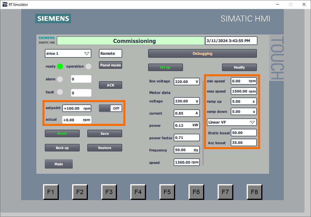
Depress the ‘Modify’ button to initiate the batch-writing process for all application parameters. Throughout this operation, the button will visually indicate ‘Modifying,’ with the background shifting to an orange hue and intermittently flashing to signify ongoing activity.
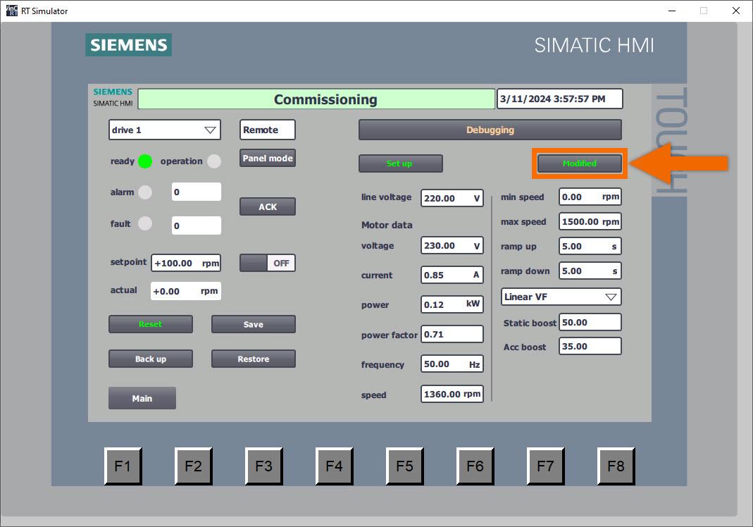
Following the writing of all parameters, the button transitions to the ‘Modified’ display, while the color of the text elegantly changes to a vibrant green hue.
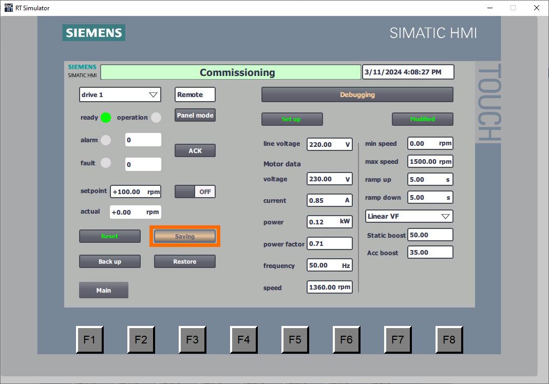
Upon completion of the commissioning process for a converter, it becomes imperative to ensure the permanent retention of all parameters to prevent their loss in the event of a power interruption. Select the ‘Save’ button to ensure the permanent storage of all parameters. Throughout this operation, the button will visually indicate ‘Saving,’ with the background shifting to an orange hue and intermittently flashing to signify ongoing activity.
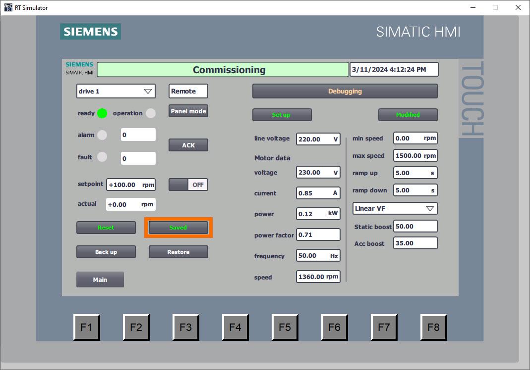
Upon completion of parameter storage, the button indicates ‘Saved’ and transitions its text color to green, signifying successful preservation.
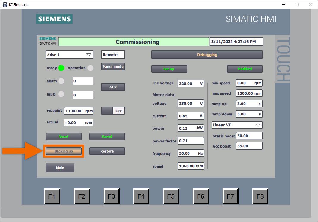
Press the ‘Backup’ button to initiate the PLC’s backup of drive parameters. Throughout this operation, the button will visually indicate ‘Backing up,’ with the background shifting to an orange hue and intermittently flashing to signify ongoing activity.
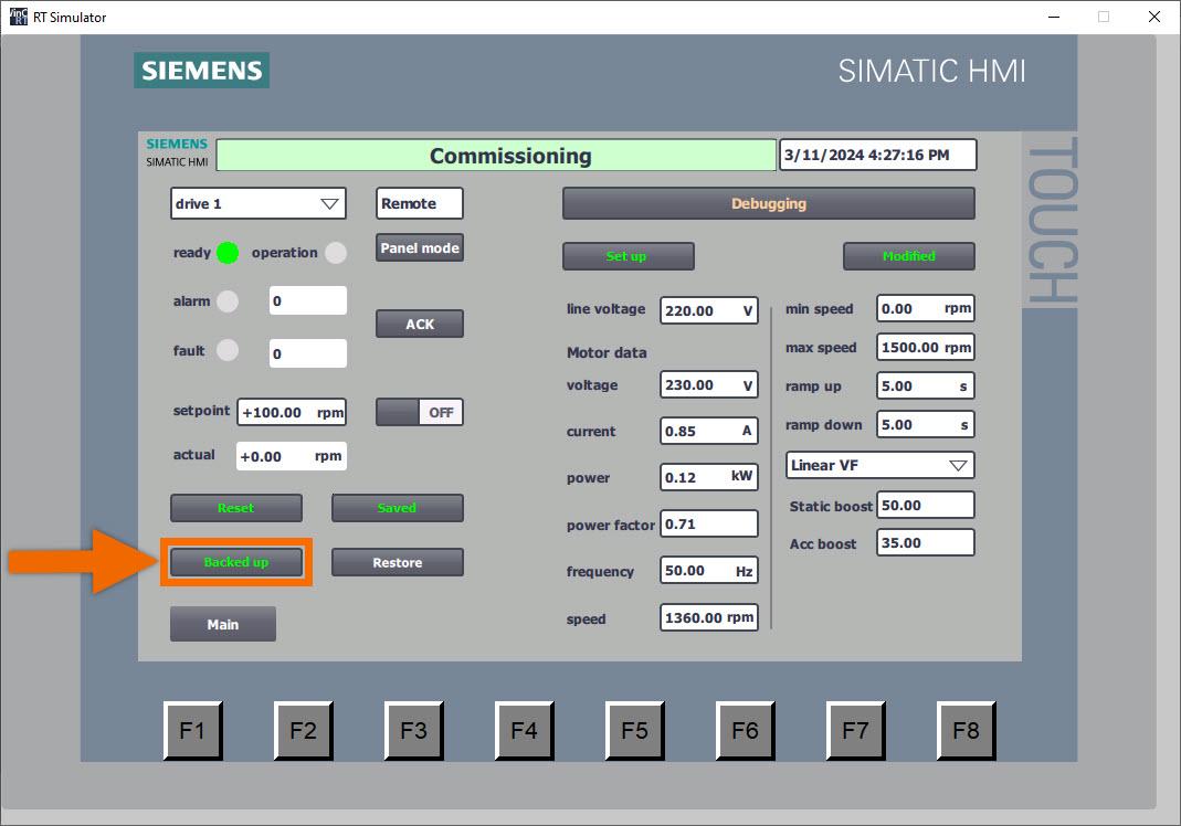
Upon completion of parameter backup, the button indicates ‘Backed up’ and transitions its text color to green, signifying successful preservation.
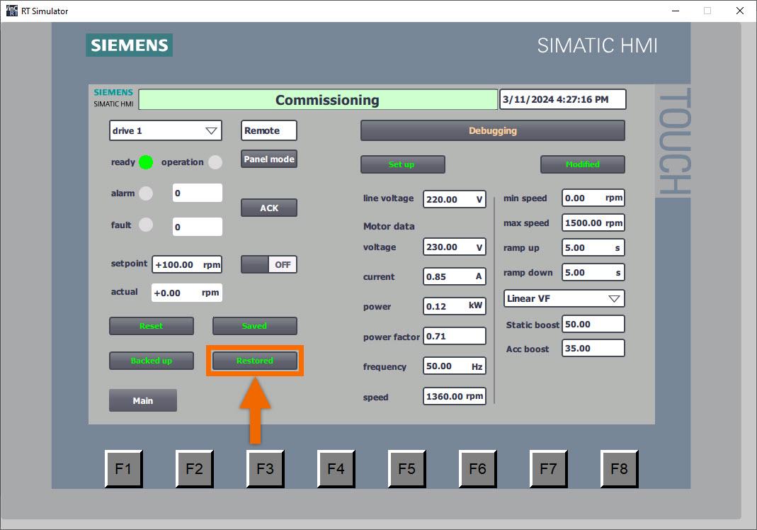
Now is the ideal moment to begin restoring parameters from the PLC. Ensure the converter is configured accurately with the appropriate IP address and device name. Press the ‘Restore Para’ button. Hold on until the button indicates the ‘Restored’ status. Engineers benefit from the remarkable convenience of this function in scenarios such as debugging similar devices or substituting new drives, enabling swift adjustment of all parameters.
In conclusion, you learned a simplified setup method for Siemens G120X/XA drives using two function blocks: ‘ParaRW’ (FB38055) and ‘EasySetupG120X/XA’ (FB38056). These blocks facilitate interaction with drive parameters and offer features like restoring factory configurations and batch-writing setup parameters. Integration of these blocks into PLC programming enables rapid converter setup and PROFINET speed regulation, enhancing operational efficiency. Additionally, the tutorial covers configuring parameters through the HMI panel, providing a comprehensive guide for efficient commissioning and maintenance of Siemens G120X/XA drives.